We use cookies to make your experience better. To comply with the new e-Privacy directive, we need to ask for your consent to set the cookies. Learn more.
Ordering Code
Invalid order code
| Qty | Unit price |
|---|---|
| 1+ | $ 87.39 |
| 10+ | $ 65.36 |
| 20+ | $ 54.85 |
| 50+ | $ 45.25 |
| 100+ | $ 39.88 |


Features:
- Highly miniaturized: 5 x 6 x 0.8 mm
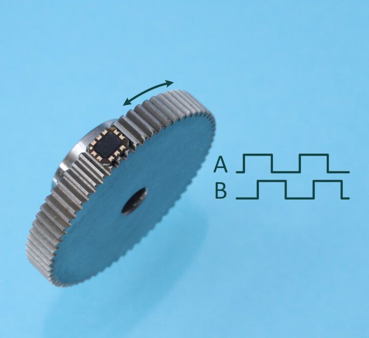
- Outputs A quad B
- Robust against oil grease, liquids, dust, particles
- Programmable resolution and max speed
- Optional with holder, cable and connector
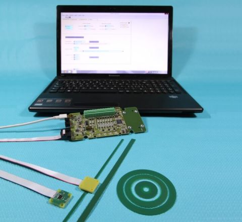
The inductive gear speed sensor ID4501G consists of a sensor chip and a gearwheel. The sensor chip is an integrated circuit in a PCB housing. It provides incremental A and B output signals in quadrature. The gearwheel is in ferromagnetic steel and has a module 0.5.
The resolution and the maximum speed of the sensor are user-programmable or can be programmed ex-factory.
|
Output signals |
A quad B |
|
Interpolation |
up to x16’384 |
|
Tooth frequency |
0 up to 25 kHz |
|
A/B frequency |
0 up to 1 MHz |
|
Supply |
5V, 10 mA |
|
Temperature |
-20 to 100°C |
|
Airgap |
0.1 – 0.6 mm |
The inductive gear speed sensor ID4501G can be operated with a gear made of ferromagnetic material and with module 0.5. POSIC uses gears from the company NOZAG, the datasheet of these gears is under the downloads tab.
The sensor is not intended for operation with non-ferromagnetic gears.
The sensor is not intended for operation with gears with module < 0.4 or module > 0.6.
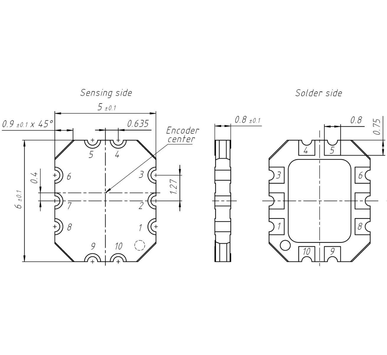
Encoder dimensions (mm).
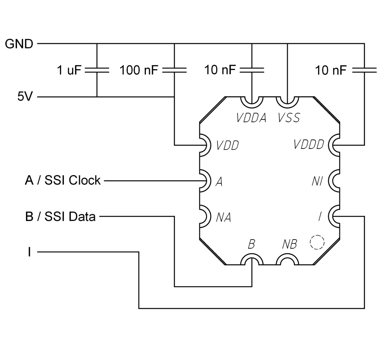
Recommended schematic.
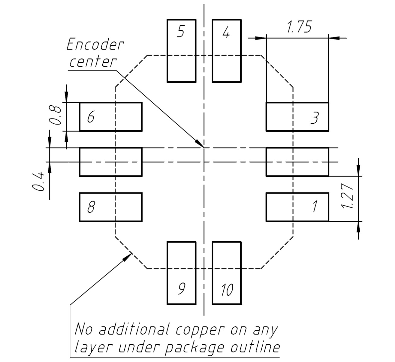
Recommended footprint.
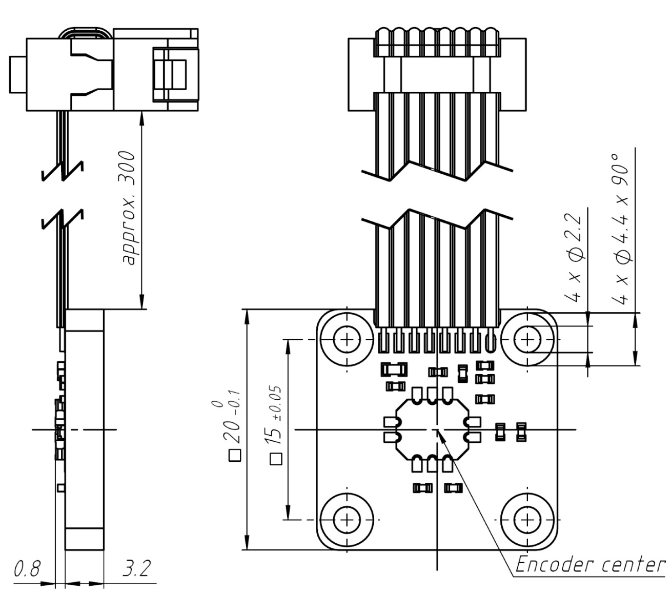
Dimensions (mm) of ID4501 encoder on encoder-holder type A with flat cable (pitch 1.27 mm) and 8-pin DIN41651 connector.
Related Products