We use cookies to make your experience better. To comply with the new e-Privacy directive, we need to ask for your consent to set the cookies. Learn more.
Technology
|
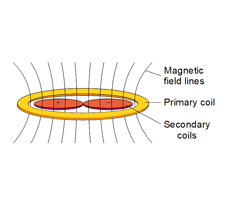
Working principle of a differential transformer A POSIC encoder is in fact a differential transformer of which the coupling between primary and secondary coils is modulated by a ferromagnetic of electrically conducting object (codewheel, scale, gear ...). The primary coil of the transformer generates a high-frequency magnetic field (1 – 2 MHz). The two secondary coils are arranged in a differential configuration that is perfectly symmetric with respect to the primary coil. The AC magnetic field generated by the primary coil induces in each of the secondary coils a voltage according to Faraday’s law:
|
 |
|
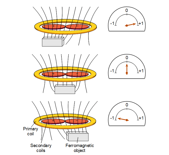
Ferromagnetic object When a ferromagnetic object is present within the magnetic field generated by the primary coil, the field is attracted by that object. If the magnetic field changes, but remains symmetrical, the voltage induced in the secondary differential coil pair remains zero (middle image to the right). However, if the object disturbs the symmetry, a non-zero signal is induced in the differential coil pair (upper and lower images to the right). Examples of ferromagnetic materials are steel and ferrites. |
 |
|
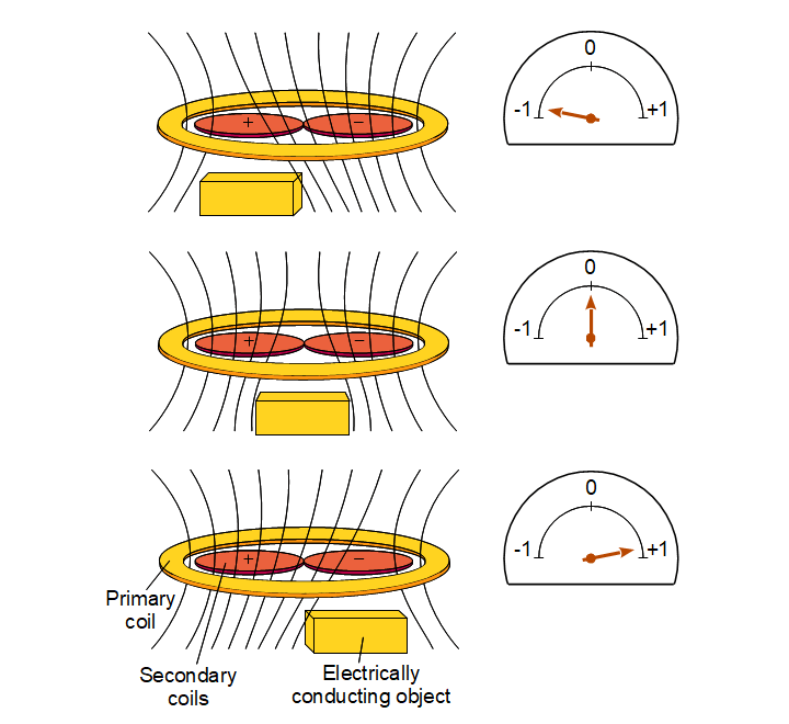
Electrically conducting object When an electrically conducting object is present within the magnetic field generated by the primary coil, the magnetic field is rejected by that object. This is due to the eddy-currents generated in the conducting object. If the magnetic field changes, but remains symmetrical, the voltage induced in the secondary differential coil pair remains zero (middle image to the right). However, if the object disturbs the symmetry, a non-zero signal is induced in the differential coil pair (upper and lower images to the right). Examples of good electrical conductors are aluminium, brass, copper, silver, gold. |
 |
|
Robustness of POSIC's differential transformer The POSIC differential inductive sensor is extremely insensitive to perturbations by external sources (magnetic and electromagnetic) because of two reasons:
|
|
|
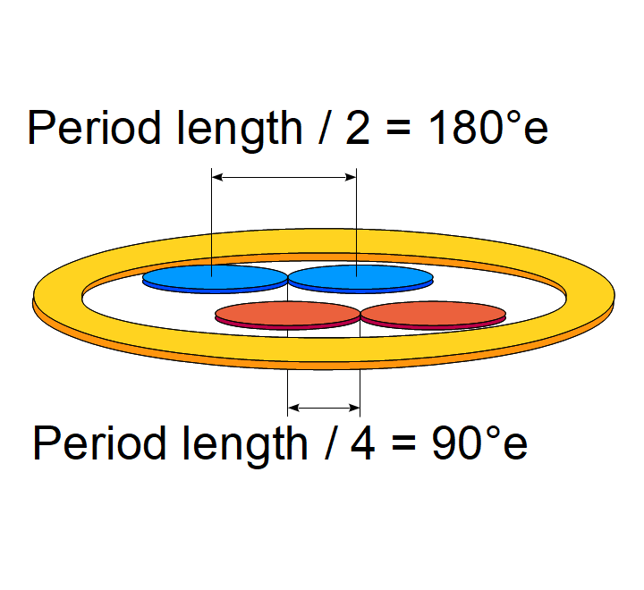
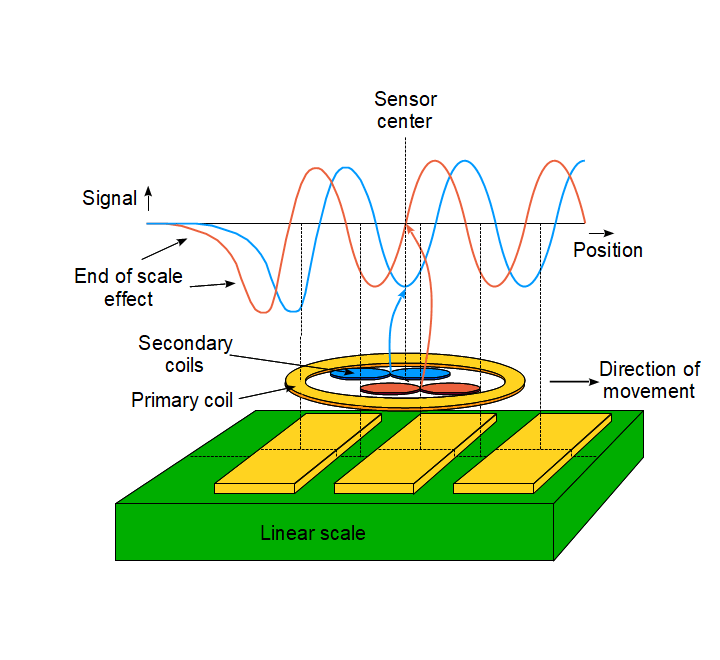
Dual-channel inductive sensor If the ferromagnetic or the electrically conducting objects discussed above are moved from left to right in front of the sensor, a sinusoidal signal results. A POSIC encoder contains two differential pairs of secondary coils, which are geometrically shifted with respect to each other, as shown in the figure to the right. The POSIC targets (codewheels and linear scales) consist of a repetition of copper stripes with a pitch (period length) of 1.2 mm. The position of the two sets of differential coil pairs on the sensor-chip is such that the two resulting sinusoidal signals have a phase-shift of 90 degrees, in other words, the resulting signals are a sine and a cosine. |
 |
|
Sine and Cosine signals When the object in front of the sensor is a repetitive pattern of ferromagnetic or electrically conducting stripes, the period of which corresponds to the coil-geometry of the sensor, the sensor output signals correspond to a sine wave for first channel and a cosine wave for the second channel. This is illustrated in the figure to the right. This figure also shows that the output signals become non-linear and eventually go to zero when the end of the scale is approached, which means that the scale should be one period longer than the actual measurement range. |
 |
|
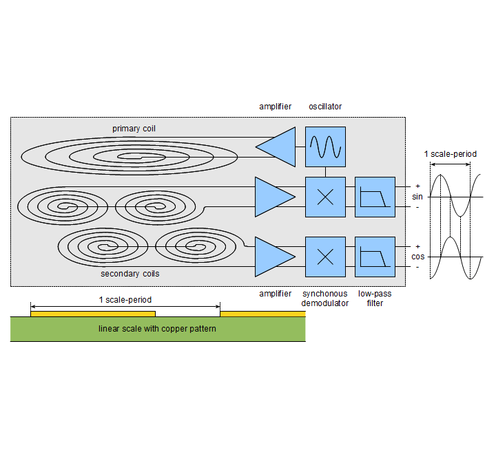
Analog sensor electronics The figure to the right shows the block diagram of the inductive sensor. An oscillator followed by an amplifier injects a high-frequency current into the primary coil. This creates a time-varying magnetic field, which is coupled into the secondary coils. The coupling between primary and secondary coils is modulated by the linear scale drawn below the block diagram. The differential signal generated by the detection coils is amplified and synchronously demodulated using the carrier frequency of the oscillator. After low-pass filtering, the analog signal is available at the output, typically in the form of a sine and a cosine signal. |
 |
|
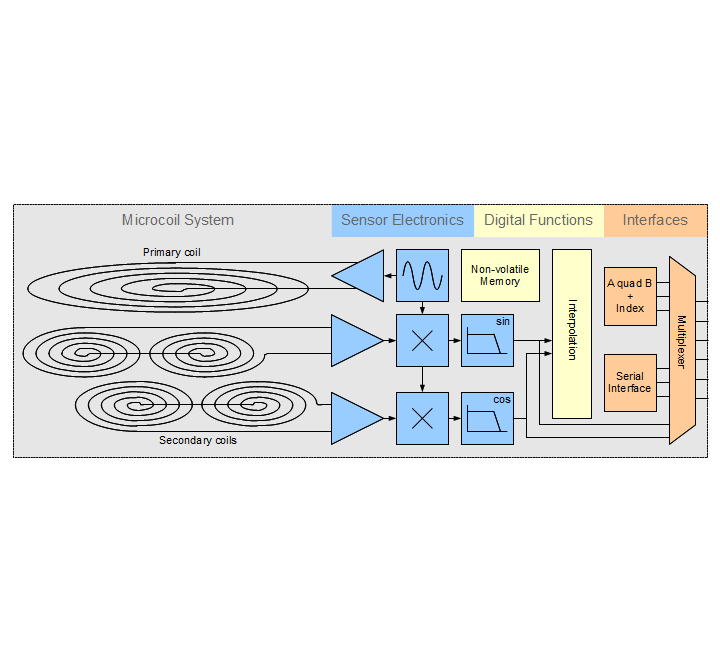
Digital sensor electronics The figure to the right shows the complete block diagram of the sensor-chip, including the primary and secondary coils, the sensor-electronics, the digital functions and the interfaces. The sine and cosine signals can be made available as output signals or can be interpolated, leading to an incremental A quad B output signal with a resolution up to 12 bits per period.Due to mounting tolerances between encoder and codewheel or scale, a certain non-linearity may occur. POSIC’s encoders contain a LookUp Table with 256 entries that can be used to correct non-linearities after mounting of the encoder and its codewheel or scale into the application. |
 |
|
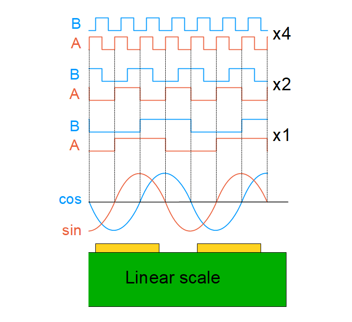
Interpolation The figure to the right shows a part of a linear scale and the resulting sine and cosine signals as well as the digital A quad B signals for interpolation factors x1 (4 states per period = 2 bit), x2 (3 bit) and x4 (4 bit). For linear scales, the interpolation factor can be adjusted from x 1 = 2 bit up to x 1024 = 12 bit per period (1 period = 1.2 mm). At 12 bit interpolation, the resulting resolution is 1.2 mm/4096 = 0.3 um. For a standard codewheel with 64 periods per revolution, the interpolation can be adjusted from x 2 up to x 64 per period, leading to a angular resolution of 128 CPR = 9 bit up to 4096 CPR = 14 bit. |
 |
|
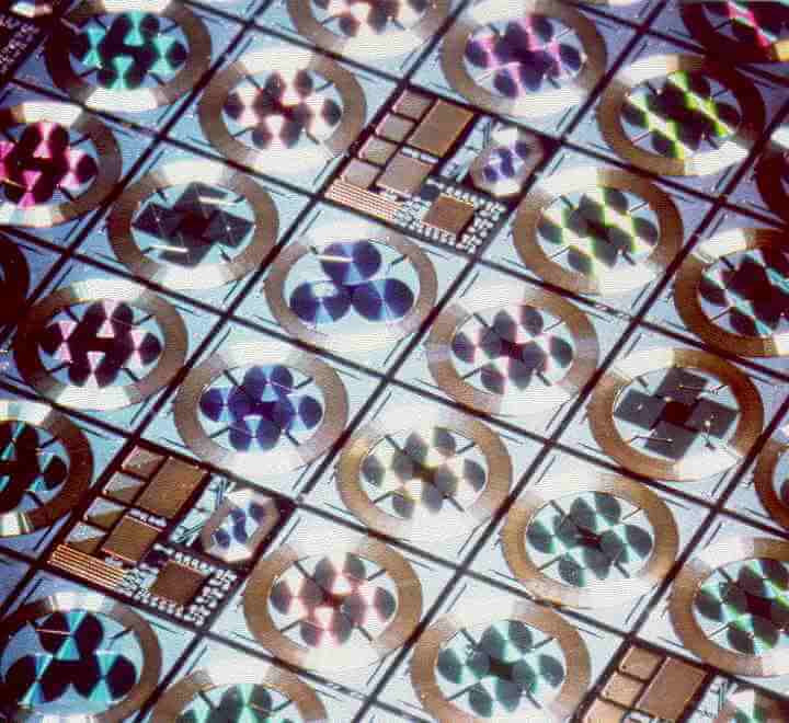
Sensor fabrication POSIC’s sensors are very compact and suitable for high-volume production because the sensor coils and the associated electronics are all integrated in a single silicon chip.The structure of a sensor can be observed in the figure to the right: the large round structures are the primary coils and the smaller round structures inside the primary coils are the detection coils. These have multiple colors because of optical interference (the pitch of the windings is in the same range as the wavelength of visible light) |
 |
|
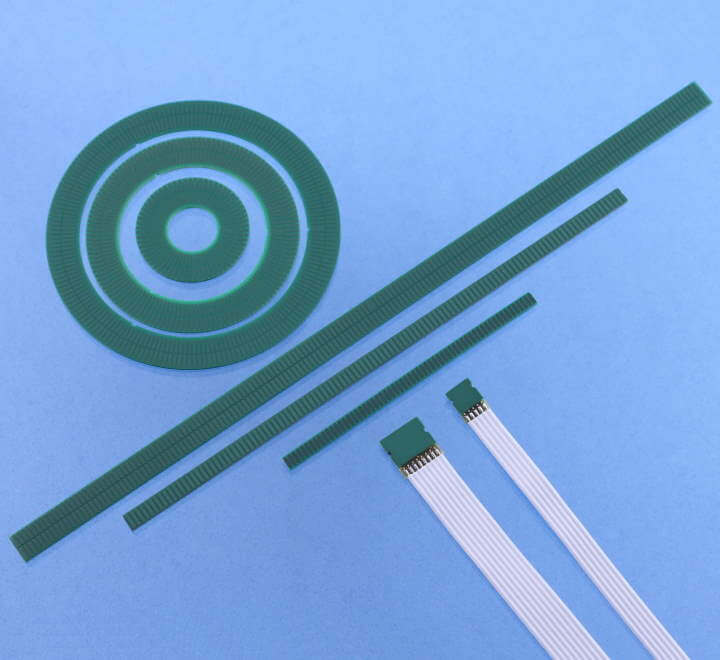
Targets: codewheels and linear scales The overall performance of an encoder depends not only on the sensor element, but also on the target. A target is characterized by three parameters:
These three parameters have an important influence on the sensor performance in terms of resolution, sensor-target distance, linearity, repeatability, maximum speed etc. POSIC has developed a series of targets for optimal performance in combination with its sensors/encoders. These targets consist of a Printed Circuit Board (PCB) with copper stripes and come in the form of codewheels for rotary applications and scales for linear applications. |
 |
|
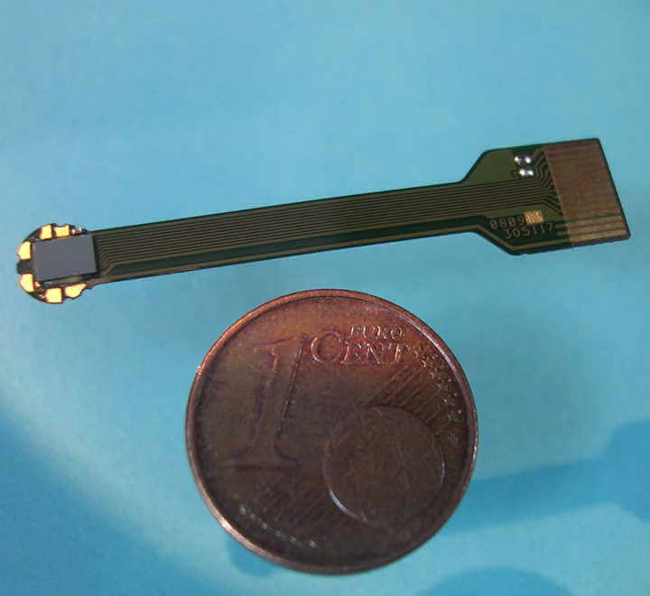
Customization POSIC offers the possibility to customize an encoder and a codewheel or linear scale to customer requirements. Examples:
|
 |
|
Features
|
|


